
Cadence Virtuoso ADE Assembler: Hierarchical Multi-Corner Simulation Management for Analog IC Design
Analog IC designers face a persistent challenge: verifying circuit performance not just at a single operating point, but across the full combinatorial space of process corners, supply voltages, and temperatures (PVT). Cadence Virtuoso's ADE Assembler (formerly ADE XL) is the industry-standard environment for orchestrating this complexity, enabling engineers to define, run, and analyze thousands of simulation sweeps from a single, structured workspace. This article examines the ADE Assembler workflow in depth—covering corner definition, parametric sweeps, specification-driven checks, and results management—with practical guidance for analog and mixed-signal (AMS) design teams.
Why Multi-Corner Simulation Matters
A transistor-level circuit that meets specifications at the nominal (TT/1.8 V/27 °C) corner can fail catastrophically at the slow-slow (SS) corner under low supply and high temperature, or exhibit excessive power consumption at the fast-fast (FF) corner. Regulatory standards such as AEC-Q100 for automotive ICs mandate verification across a defined set of corners, and foundry PDKs typically ship with 5–27 pre-characterized corners. Without a systematic framework, managing these runs manually in ADE L or ADE GXL quickly becomes error-prone and unscalable.
ADE Assembler addresses this by separating what to simulate (tests) from how to vary it (corners and sweeps) and what to check (specifications), then automating the entire matrix.
Core Concepts: Tests, Corners, and Specifications
Tests
A test in ADE Assembler is a self-contained simulation configuration: a schematic view, a simulator (Spectre, Spectre APS, or UltraSim), an analysis type (DC, AC, transient, noise, PSS, etc.), and a set of outputs. Tests are reusable across projects and can be organized into a hierarchy—for example, a top-level "Full Characterization" suite that references sub-suites for DC bias, AC bandwidth, and noise figure.
Corners
Corners are defined in the Corner Manager, which maps symbolic names (e.g., ss_1p62v_125c) to model file sections, global parameter overrides, and temperature settings. ADE Assembler supports:
- Process corners – model file section switching (TT, FF, SS, SF, FS)
- Voltage corners –
vddparameter swept from 1.62 V to 1.98 V for a 1.8 V nominal supply - Temperature corners – −40 °C, 27 °C, 85 °C, 125 °C
- Monte Carlo – statistical variation using foundry mismatch and process spread models
Corners can be grouped into corner groups (e.g., "Automotive 5-corner" vs. "Extended 27-corner") so that quick sanity checks use a reduced set while sign-off runs use the full matrix.
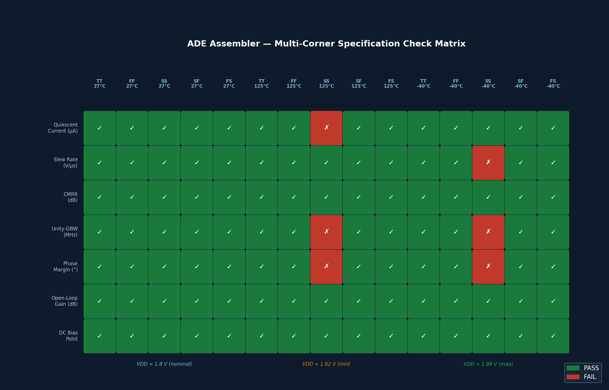
Specifications
Each output can be assigned a specification check: a pass/fail criterion with a minimum, maximum, or target value. ADE Assembler color-codes results (green/red) and generates a spec summary table that immediately highlights failing corners—eliminating the need to manually scan hundreds of waveforms.
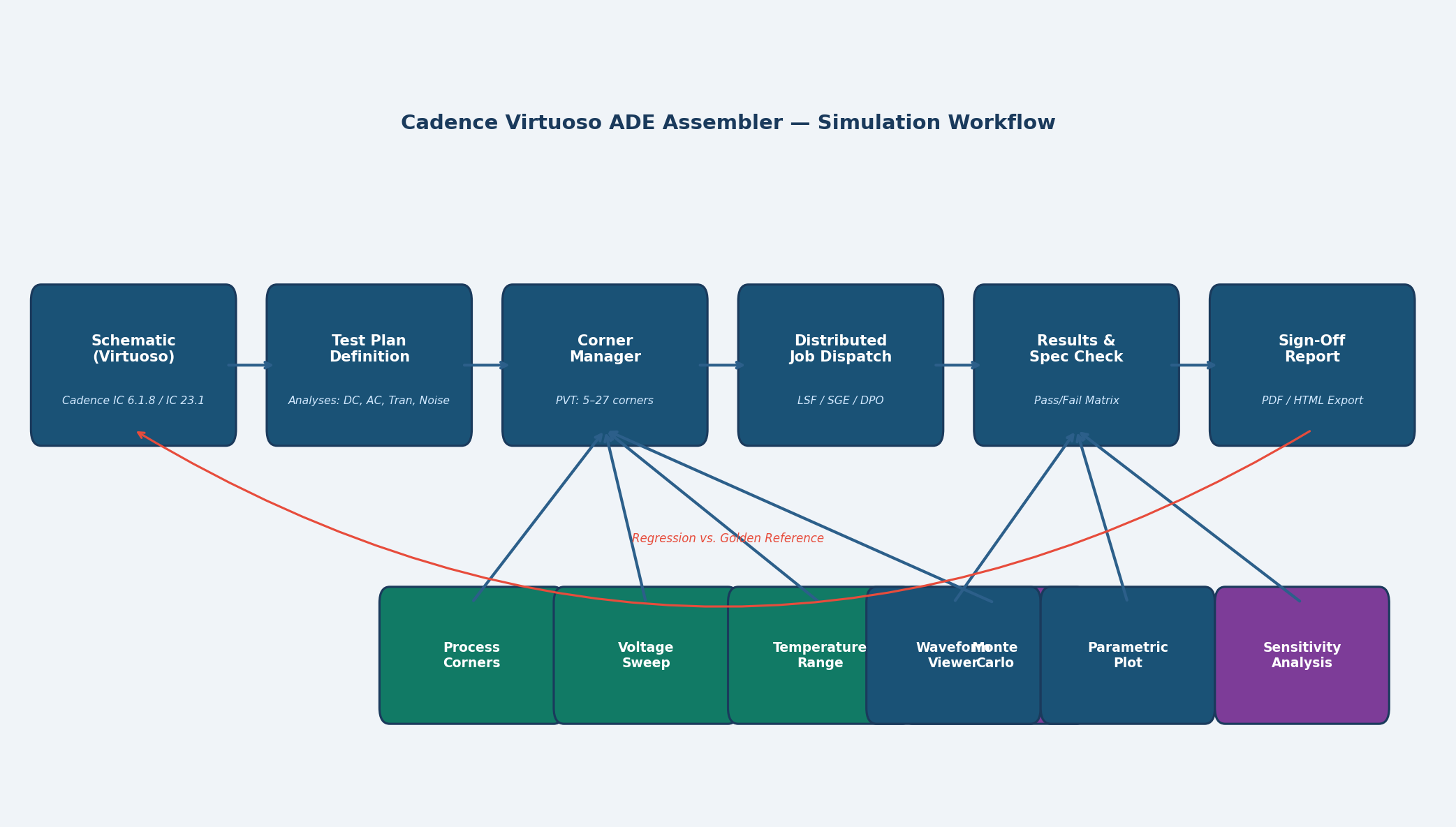
Practical Workflow: From Schematic to Sign-Off
Step 1 – Create the Test Plan
Open ADE Assembler from the Virtuoso schematic window (Launch → ADE Assembler). Create a new plan and add tests by importing existing ADE L states or building new ones. Assign each test a descriptive name and verify that all outputs (e.g., gain_dB, phase_margin, idd_quiescent) are correctly probed.
Step 2 – Define the Corner Set
In the Corner Manager, import the foundry-provided corner file (typically a .sdb or .corners file shipped with the PDK). Add voltage and temperature axes. For a 5-corner × 3-voltage × 4-temperature matrix, ADE Assembler will schedule 60 simulation jobs per test.
Step 3 – Configure Distributed Computing
ADE Assembler integrates with LSF, SGE, and Cadence Distributed Processing Option (DPO) to dispatch jobs to a compute farm. Enable DPO under Setup → Job Specification, set the queue name, and specify the maximum number of concurrent licenses. A 60-corner transient run that takes 8 hours sequentially can complete in under 30 minutes on a 32-node farm.
Step 4 – Run and Monitor
Click Run All (or Run Selected for a subset). The Job Monitor panel shows real-time status for each corner/test combination. Failed jobs display the simulator error log inline, enabling rapid diagnosis without leaving the ADE Assembler environment.
Step 5 – Analyze Results
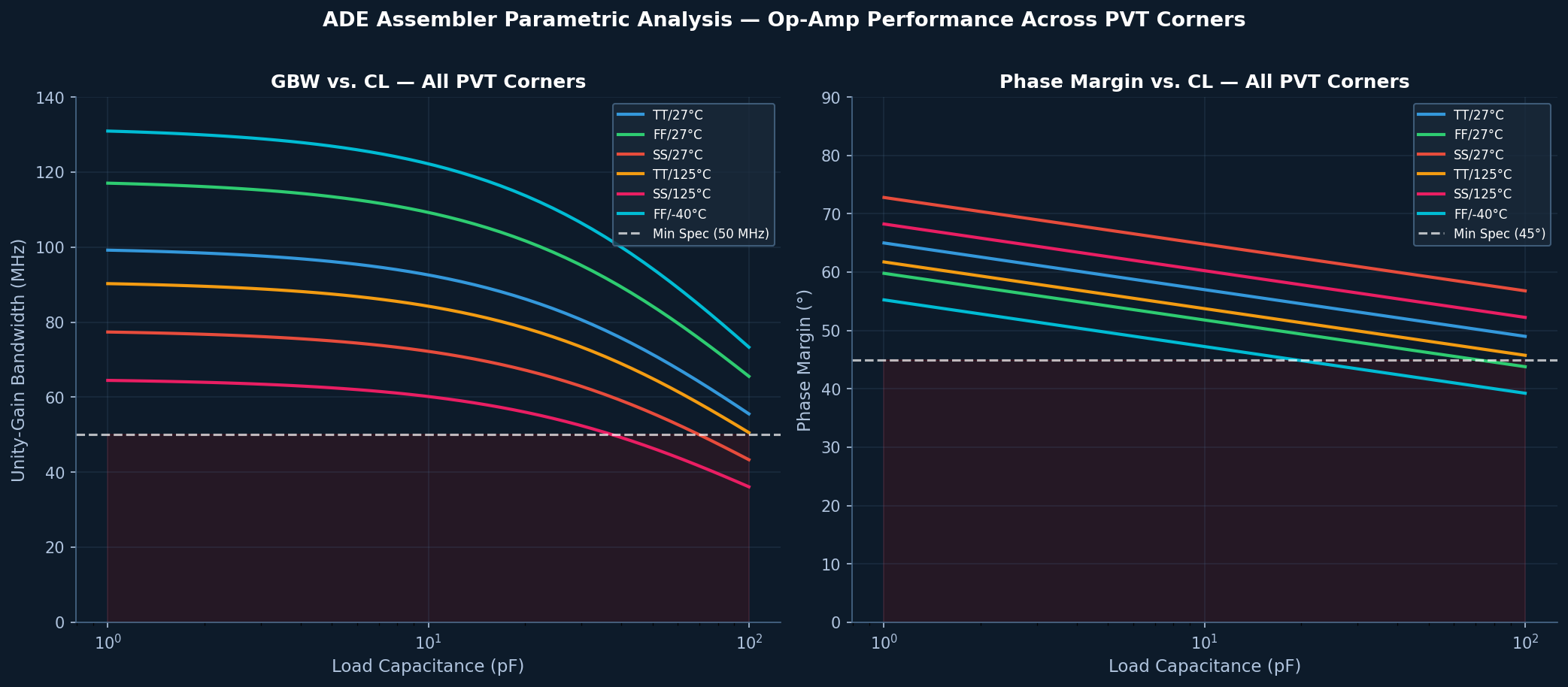
After completion, switch to the Results view. The Spec Summary table provides a pass/fail matrix across all corners. Click any cell to open the corresponding waveform in Virtuoso Visualization and Analysis (ViVA). Use the Parametric Analysis plot to visualize how a metric (e.g., unity-gain bandwidth) varies continuously across a swept parameter (e.g., load capacitance from 1 pF to 100 pF).
Advanced Features
Sensitivity Analysis
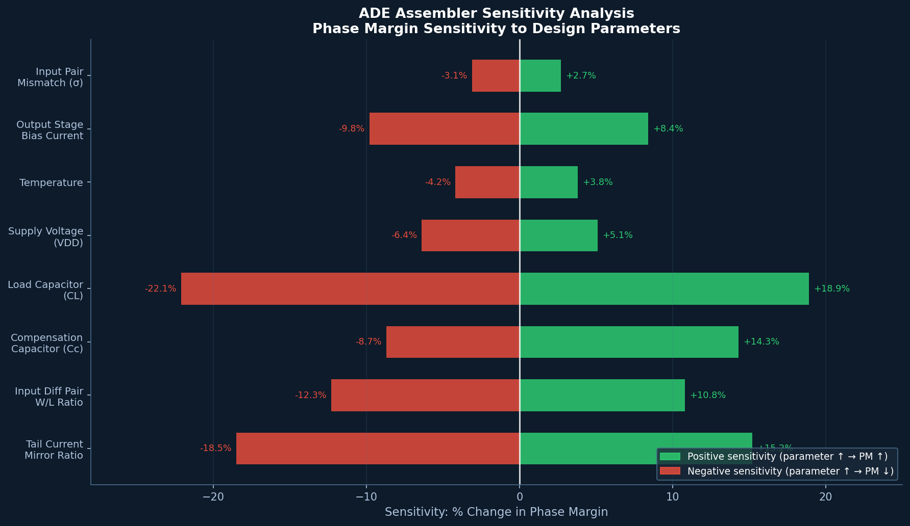
ADE Assembler's Sensitivity feature runs a design-of-experiments (DOE) sweep to identify which parameters most strongly influence a given output. This is invaluable for yield optimization: if phase margin is most sensitive to the tail current mirror ratio, the designer knows where to focus layout matching effort.
Regression and Golden Reference
Save a passing run as a golden reference. Subsequent runs automatically compare against the golden, flagging any regression—a critical capability for teams using version-controlled schematics in a PDM system such as Cadence Virtuoso IC 6.1.8 or IC 23.1.
AMS Co-Simulation
For mixed-signal blocks, ADE Assembler can invoke Xcelium for the digital portion while Spectre handles the analog, with the two simulators exchanging data through the AMS Connect Rules. This enables full-chip PVT verification without splitting the design into separate analog and digital flows.
Best Practices
- Modularize tests – Keep each test focused on one functional aspect (e.g., separate tests for open-loop gain and closed-loop step response). This makes it easier to re-run only the affected tests after a schematic change.
- Use symbolic corner names – Never hard-code model file paths in a test. Always reference the Corner Manager so that PDK updates propagate automatically.
- Set tight spec limits early – Define specifications before running, not after. Post-hoc spec setting introduces confirmation bias and defeats the purpose of automated checking.
- Archive results with the schematic – Use
File → Save Resultsto store the.adeasmblrdatabase alongside the schematic in the PDM system, ensuring full traceability for design reviews. - Leverage incremental runs – After a minor schematic change, use Run Changed to re-simulate only the corners that are likely affected, saving significant compute time.
Conclusion
Cadence Virtuoso ADE Assembler transforms multi-corner analog verification from a manual, error-prone process into a structured, automated workflow. By separating test definition, corner management, and specification checking into distinct layers, it scales gracefully from a single designer running 5-corner checks on a laptop to a 50-engineer team executing 10,000-job sign-off runs on a compute farm. For analog and mixed-signal IC teams targeting automotive, industrial, or high-reliability markets, mastering ADE Assembler is not optional—it is the foundation of a credible sign-off methodology.